

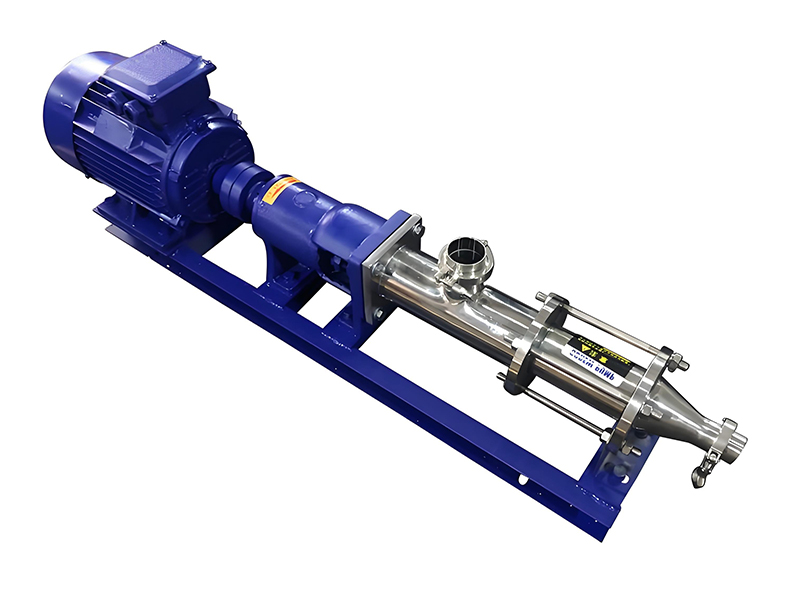
Screw pump rotors are the core components that define how a screw pump moves fluid and how efficiently it operates. By understanding rotor geometry, materials, and operating principles, engineers and users can optimize system reliability, energy consumption, and overall performance.
Screw pumps are positive displacement pumps that use one or more intermeshing screw-shaped rotors to move fluid along the pump axis. Unlike centrifugal pumps, which rely on high rotational speed and kinetic energy, screw pumps generate a continuous, low-pulsation flow through sealed cavities formed by the rotors.
The rotor is the rotating element that directly interacts with the pumped fluid. Its design determines:
Because rotor performance is so critical, optimizing screw pump rotors is a key engineering task in applications such as oil and gas, chemical processing, food and beverage, wastewater, and power generation.
Before focusing on rotors, it is important to understand the general screw pump operating principle. Screw pumps are rotary positive displacement pumps. They trap fixed volumes of fluid and transport them from the suction side to the discharge side with each rotation of the rotor set.
In all screw pump designs, the cooperation between rotors (or rotor and stator) forms a sequence of sealed cavities. When the screws rotate, these cavities progress axially, carrying the fluid with them. Because the cavities are nearly constant volume, the flow is proportional to rotational speed.
Screw pump rotors generate flow by positive displacement. The theoretical flow rate Qth is given by:
Qth = Vdisp × n
where Vdisp is the displacement volume per revolution and n is the rotational speed. Rotor geometry directly defines this displacement volume and thus the pump capacity.
As the screw rotors turn, they form cavities that are nearly sealed against backflow. These cavities progress along the rotor axis, transporting fluid from inlet to outlet. The tighter the sealing between rotors, housing, and (in single-screw designs) stator, the lower the internal leakage and the higher the volumetric efficiency.
The geometry of screw pump rotors inherently produces smooth flow with very low pulsation. Multiple cavities are in different stages of filling and discharging at any given moment. This feature reduces pressure fluctuations and mechanical stress on piping and instrumentation, especially compared with reciprocating pumps.
Different screw pump configurations use different rotor types. The main categories include:
In a single-screw pump, often known as a progressive cavity pump, the rotor is a single helical screw with a defined pitch and eccentric geometry. It rotates inside an elastomer or metallic stator with an internal profile that forms a series of cavities.
Key characteristics:
Twin-screw pumps use two intermeshing rotors, typically counter-rotating. Their synchronized motion creates sealed chambers between the screw threads and the pump casing. The fluid is transported axially from suction to discharge.
Typical features:
Triple-screw pumps have one driving screw (power rotor) and two idler screws. The idler screws rotate inside the pump housing and are driven hydrodynamically by the fluid film and mechanically by the meshing geometry.
Key points:
| Rotor Type | Number of Screws | Typical Fluid Viscosity Range | Common Applications | Pulsation Level | Solids Handling |
|---|---|---|---|---|---|
| Single-Screw (Progressive Cavity) | 1 | Medium to very high | Sludge, slurries, food pastes, polymers | Very low | Good |
| Twin-Screw | 2 | Low to very high | Multiphase oil, chemicals, hygienic fluids | Very low | Moderate (depending on clearances) |
| Triple-Screw | 3 | Low to medium (lubricating) | Lube oil, fuel oil, hydraulic oil | Very low | Poor to moderate (mainly clean fluids) |
Rotor geometry is central to how screw pump rotors contribute to fluid movement and efficiency. The main geometric parameters include:
The rotor diameter influences displacement volume and mechanical strength. A larger diameter rotor can move a greater volume per revolution but may require more torque and more robust bearings. The rotor length affects the number of stages (in progressive cavity pumps) or the number of sealing chambers along the axis.
The rotor pitch is the axial distance over which the screw profile completes one full turn. A longer pitch can increase theoretical flow but may reduce pressure capability. The number of threads or starts determines how many cavities exist simultaneously and affects flow smoothness and torque distribution.
The helix angle of the rotor profile determines how aggressively fluid is advanced per degree of rotation. A higher helix angle generally increases flow per revolution but may also influence radial forces and cavitation risk at high speeds.
The cross-sectional profile of the rotor thread (e.g., involute, trapezoidal, or custom forms) is essential for sealing and load distribution. The flank angle influences the hydrodynamic film formation between screws and between rotor and housing. Optimized profiles reduce internal leakage, minimize contact stress, and improve mechanical efficiency.
In many screw pumps, the rotors are designed to operate with very small clearances rather than metal-to-metal contact. These clearances act as throttling gaps. If they are too large, internal leakage increases and volumetric efficiency falls. If they are too small, risk of contact, wear, or seizure increases, especially when pumping contaminated or viscous fluids.
Screw pump rotors contribute to fluid movement through a combination of geometric design and rotational motion. The working mechanism can be broken down into three main steps: suction, sealing and conveying, and discharge.
At the suction side, as the rotor turns, new cavities open. The volume of these cavities increases, reducing the local pressure and allowing atmospheric or system pressure to push fluid into the pump. The rotor surface and screw flanks help draw the fluid in smoothly, even for highly viscous or shear-sensitive liquids.
Once the cavities are filled with fluid, further rotation moves the sealed chambers axially. The rotor design ensures that each chamber remains effectively closed in the radial and circumferential directions, preventing backflow under normal operating conditions. The progressive nature of this process results in a near-constant flow.
At the discharge side, rotor geometry forces the filled cavities to collapse or merge into the outlet channel. As the cavity volume decreases, fluid is expelled at elevated pressure. Because multiple cavities discharge in sequence, the resulting flow is steady and continuous.
Volumetric efficiency is determined by how well the rotor design restricts internal leakage. Potential leakage paths include:
Advanced rotor designs use carefully defined clearances, optimized helix profiles, and, in some cases, coatings or elastomeric stators to minimize leakage and improve volumetric efficiency.
Overall screw pump efficiency is the product of volumetric efficiency and mechanical efficiency. Rotor design influences both.
Volumetric efficiency describes how much of the theoretical displacement volume is actually delivered as useful flow. Rotor factors that affect volumetric efficiency include:
A well-designed screw pump rotor provides consistent sealing along its entire length, maintaining high volumetric efficiency across a wide range of pressures and viscosities.
Mechanical efficiency is related to friction losses and power consumption. Rotor geometry and materials determine:
Hydraulic efficiency is influenced by how fluid flows around the rotor threads. Smooth transitions, optimized helix angle, and minimal turbulence improve hydraulic efficiency and reduce heat generation.
Because screw pump rotors directly define the energy needed to move a given volume at a given pressure, optimized rotor design can significantly reduce operating costs. Modern rotor profiles can reduce power draw, lower temperature rise, and extend lubricant life in the system.
The choice of rotor materials and surface treatments is critical for longevity, corrosion resistance, and efficiency. The interaction between rotor surface and pumped fluid can lead to wear, pitting, or corrosion if not properly matched.
To enhance performance, screw pump rotors often receive surface treatments such as:
In single-screw pumps, the rotor-stator material pairing is especially important. A hard metal rotor is typically paired with a compliant elastomeric stator. This combination allows the rotor to form tight sealing lines without excessive wear. The selected elastomer must be chemically compatible with the pumped fluid and must tolerate the operating temperature range.
Well-engineered screw pump rotors offer many advantages compared with other positive displacement and dynamic pump types. These advantages are strongly tied to rotor geometry, material selection, and manufacturing precision.
The multi-chamber action of screw pump rotors produces almost pulse-free flow. This characteristic is crucial for applications where constant flow is required to protect downstream equipment, such as flow meters, heat exchangers, and sensitive process units.
Screw pump rotors can handle an exceptionally wide range of viscosities, from thin solvents to heavy crude oils and slurries. The positive displacement mechanism provides consistent flow even as viscosity changes, making these pumps attractive for processes with variable fluid properties.
The strong suction characteristics of screw pumps stem from the rotor’s ability to evacuate the cavities and maintain low NPSH requirements. This feature is critical in tank stripping, ship unloading, and vacuum-assisted systems.
Twin-screw rotors are especially suitable for multiphase mixtures containing gas and liquid. The rotor geometry can compress and transport gas–liquid mixtures without losing prime, enabling stable operation in production and transfer systems.
Because screw pump rotors move fluid in a smooth, continuous manner, shear rates can be lower than in centrifugal pumps. This gentle handling is beneficial for emulsions, biological products, food ingredients, and other shear-sensitive materials.
Several key performance parameters are directly influenced by screw pump rotor characteristics. Understanding these helps in sizing, selecting, and evaluating screw pumps.
Theoretical displacement per revolution depends on rotor diameter, pitch, and number of threads. Effective displacement decreases slightly due to internal slip. For design purposes, manufacturers often provide performance curves that relate flow rate to speed and differential pressure.
Pressure capability is determined by the sealing effectiveness of the rotor design and the strength of the rotor and housing. Progressive cavity pumps can achieve significant discharge pressures by increasing the number of stages (rotor–stator pairs in series). Multi-screw pumps typically have design limits that reflect rotor bending, bearing capacity, and allowable torque.
Power consumption P is influenced by flow rate, pressure rise, and efficiency according to:
P = (Q × Δp) / (η × 367) (for SI units, with Q in m3/h, Δp in bar, P in kW)
Rotor design improvements that reduce slip and friction allow operation at lower power for the same duty, improving overall energy efficiency.
Rotor balance, profile accuracy, and manufacturing tolerances influence noise and vibration levels. Properly engineered rotors run with minimal vibration, reducing bearing loads and extending equipment life.
While exact rotor specifications vary by pump model and manufacturer, the following table summarizes typical ranges for Industrial screw pump rotors. These values are approximate and serve only as general guidelines.
| Parameter | Single-Screw Rotor | Twin-Screw Rotor | Triple-Screw Rotor |
|---|---|---|---|
| Rotor Diameter Range | 20 – 300 mm | 30 – 250 mm | 20 – 200 mm |
| Rotor Length Range | 0.2 – 6 m (multi-stage) | 0.3 – 3 m | 0.2 – 2 m |
| Typical Speed Range | 50 – 600 rpm | 200 – 3600 rpm | 600 – 3600 rpm |
| Viscosity Handling | Up to >1,000,000 cP | 1 – 1,000,000 cP | 1 – 10,000 cP (lubricating) |
| Max Differential Pressure | Up to 48 bar or more (multi-stage) | Up to ~80 bar (design dependent) | Up to ~100 bar (clean, lubricating) |
| Typical Materials | Alloy steel, stainless steel | Alloy steel, stainless, duplex | Alloy steel, case-hardened steel |
| Surface Treatment | Chrome plated, polished | Nitrided, coated, polished | Nitrided, hardened, superfinished |
Specific industries use screw pump rotors optimized for their fluids and operating conditions. Rotor configuration and materials are chosen to balance efficiency, reliability, and service life.
In upstream production, twin-screw and progressive cavity rotors handle multiphase mixtures of crude oil, gas, water, and solids. Rotor designs emphasize gas-handling capability, abrasion resistance, and tolerance for fluid property changes over the field life.
Triple-screw pump rotors are common for lubricating oil circulation, seal oil, and fuel oil transfer. These rotors prioritize quiet operation, high reliability, and precise flow delivery at stable pressures.
Twin-screw rotors in hygienic designs handle dairy products, sauces, syrups, and other sanitary fluids. Rotors often use stainless steel with polished surfaces and are designed for clean-in-place (CIP) procedures to maintain hygiene while preserving gentle fluid handling.
Single-screw progressive cavity rotors handle sludge, biosolids, and other abrasive, high-solids liquids. Rotor geometry is optimized to maintain flow despite solids, while material and coating choices resist abrasion and chemical attack.
Designing efficient screw pump rotors involves balancing many factors. Engineers must consider hydraulic performance, mechanical integrity, manufacturability, and economic constraints.
Rotors are tailored to the target fluid’s viscosity, lubricity, abrasiveness, and chemical characteristics. For example:
At higher pressures, rotor deflection can lead to uneven clearances and increased wear. Rotor diameter, material modulus, and support bearing design must be coordinated to maintain stable running and consistent clearances.
Temperature changes in the pumped fluid and environment can cause thermal expansion of the rotor and housing. Designers must calculate thermal growth to ensure that desirable clearances are maintained during operation and that the pump can start safely from ambient conditions.
Rotor performance is highly sensitive to machining accuracy and surface finish. Advanced manufacturing methods such as precision grinding, CNC milling, and coordinate measurement verification are often employed to ensure consistent rotor geometry and optimize sealing lines.
When selecting a screw pump for a particular application, paying attention to rotor-related aspects can significantly improve system reliability and efficiency.
Selection should consider corrosion resistance, wear resistance, and compatibility with any cleaning or sterilization processes. For aggressive media, duplex or coated rotors may be justified despite higher initial cost due to lower life-cycle cost.
Higher speeds can reduce pump size for a given flow but may increase wear and reduce rotor life, especially in abrasive service. Balancing speed, rotor diameter, and material hardness is essential for long-term efficiency.
Even the best-designed screw pump rotors experience wear over time. Good maintenance practices are essential to preserve efficiency and reliability.
Common symptoms of rotor degradation include:
To extend rotor life and maintain efficiency:
Screw pump rotors are fundamental to how these pumps achieve controlled fluid movement and high efficiency. Through carefully engineered geometry, material selection, and manufacturing quality, rotors provide:
In any screw pump installation, attention to rotor type, dimensions, materials, and clearances is crucial for maximizing productivity, reducing energy consumption, and ensuring reliable operation. A detailed understanding of how screw pump rotors contribute to fluid movement and efficiency enables more informed decisions when designing, specifying, and operating pumping systems in industrial environments.
```

Copyright ? Jiangsu Longjie Pump Manufacturing Co., Ltd.


 Phone
Phone
Comment
(0)